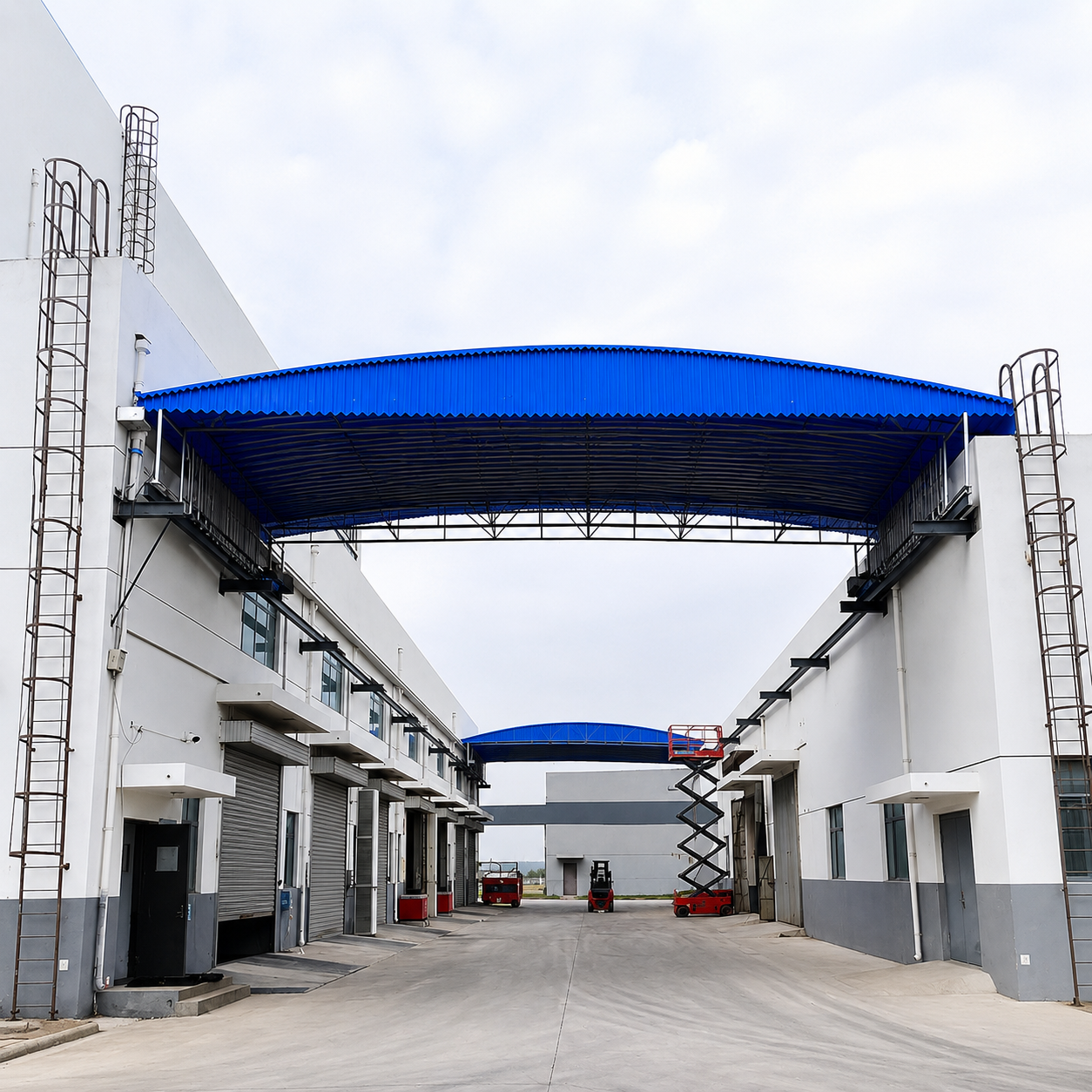
A motorized retractable dome canopy has become an increasingly popular roofing solution for factories, warehouses, sports facilities, and commercial spaces due to its flexible opening and closing mechanism, cost-effectiveness, and ability to maximize usable space. However, for the system to operate reliably over decades, every component from the structural steel frame and guide rails to the wheel assemblies and roofing materials must be carefully engineered and manufactured in accordance with industry standards.
So, how is a motorized retractable dome canopy constructed? How does its operating mechanism work? This article provides a comprehensive overview of its structural components, technical specifications, and the role each part plays in ensuring safe and efficient operation.
What Is a Motorized Retractable Dome Canopy?
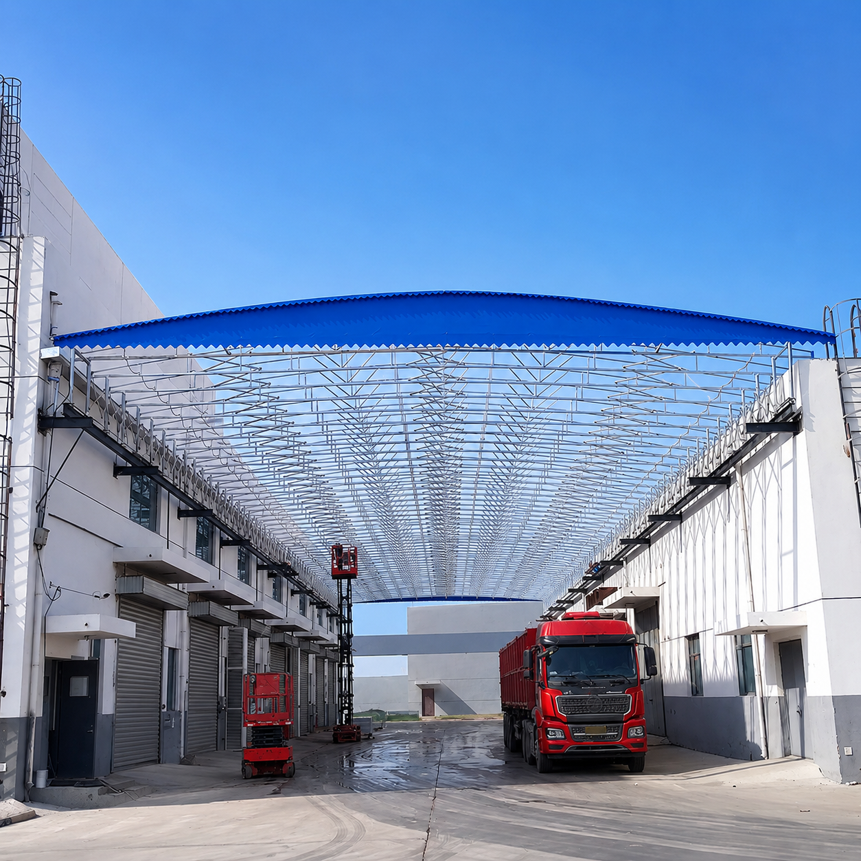
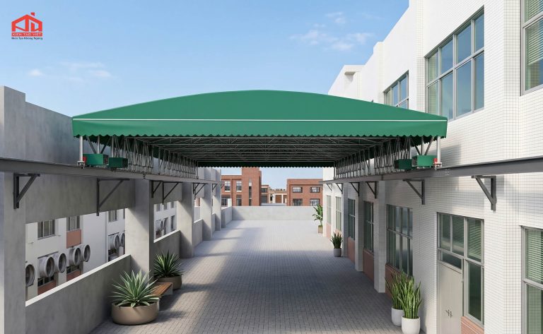
A motorized retractable dome canopy is a movable roofing system that can open, close, or retract smoothly using an electric drive system and guide rails. Unlike conventional fixed roofs, this canopy is designed with multiple curved structural modules of progressively smaller sizes that slide and nest into one another, allowing the roof to retract compactly and maximize open space.
Today, motorized retractable dome canopies are widely used in a variety of applications, including:
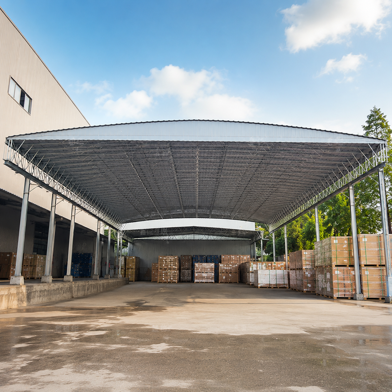
– Manufacturing factories
– Logistics warehouses
– Parking facilities
– Swimming pools
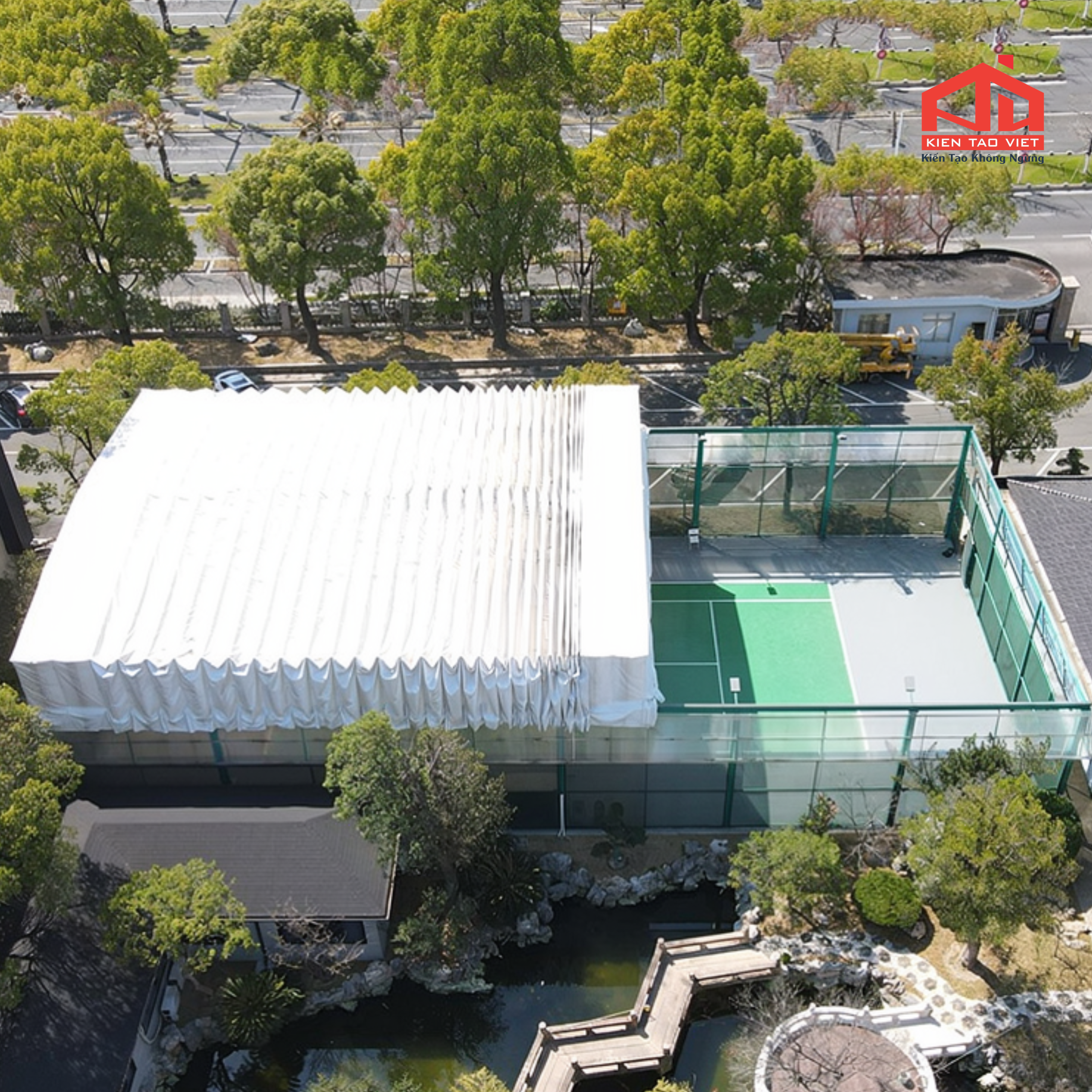
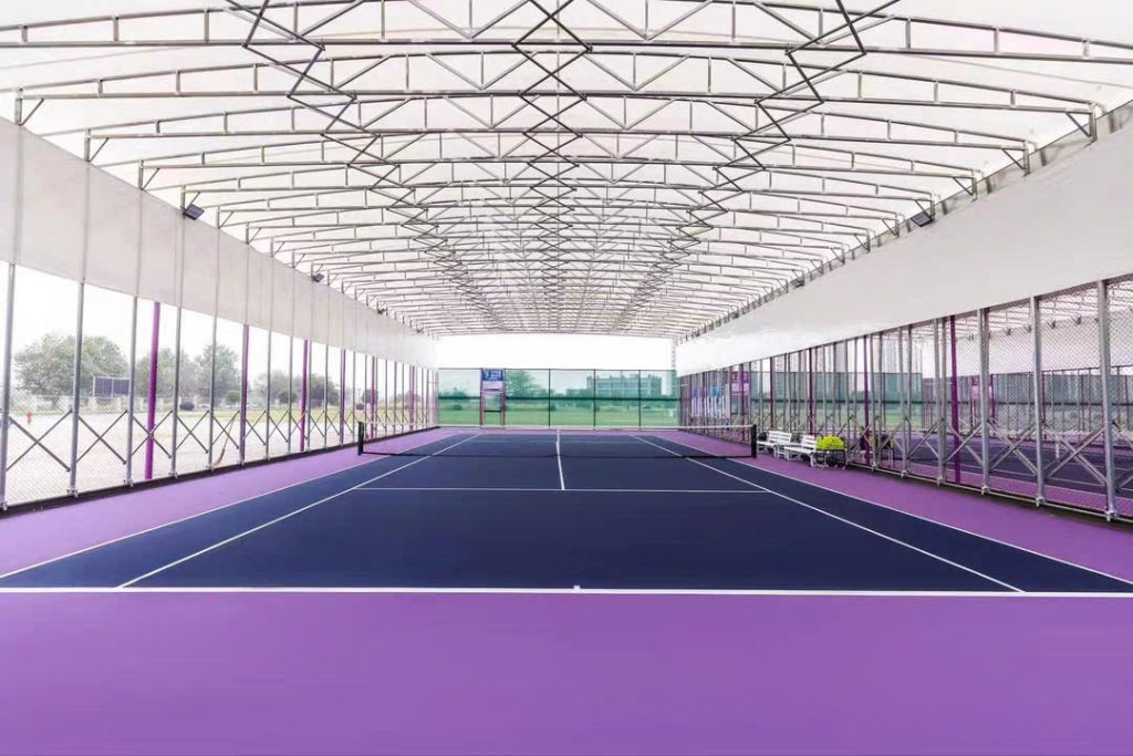
– Tennis courts and pickleball courts
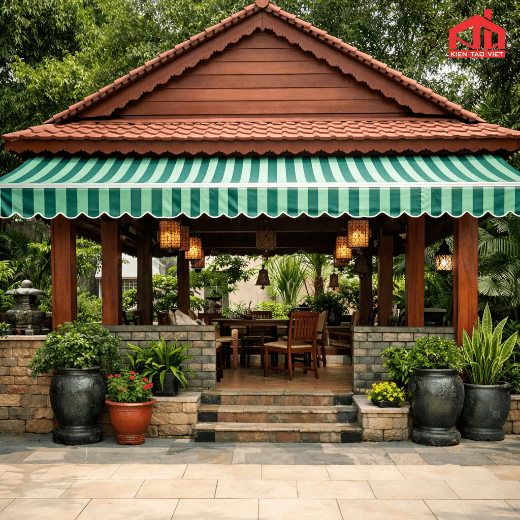
– Cafés
– Restaurants
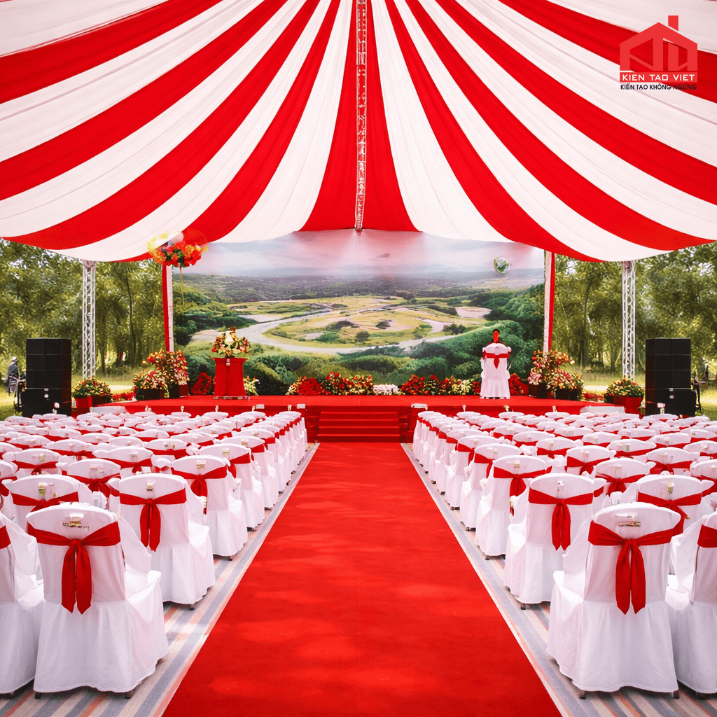
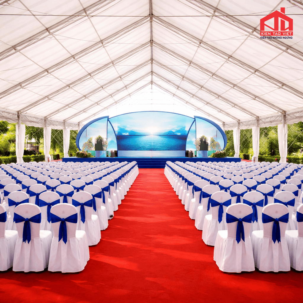
– Event venues
– Educational institutions
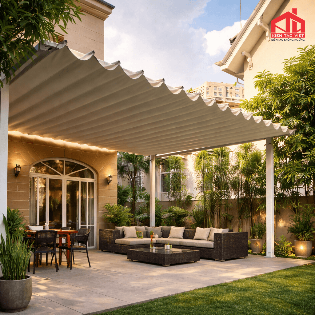
One of the greatest advantages of this roofing system is its ability to close automatically during rain or intense sunlight and open when natural ventilation and daylight are desired. This flexibility helps reduce energy consumption, improve indoor comfort, and maximize the operational efficiency of the facility.
Detailed Structure of a Motorized Retractable Dome Canopy
A standard motorized retractable dome canopy typically consists of 10 main structural components, each playing a vital role in ensuring the system’s strength, stability, and smooth operation.
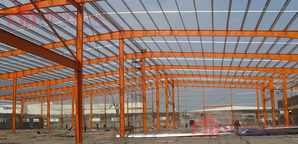
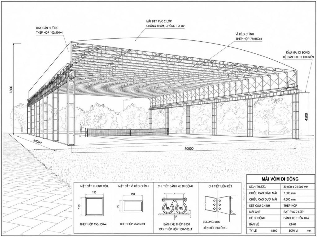
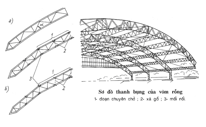
Structural Arch Frame – The Backbone of the Entire System
The structural arch frame is the most critical component of the canopy, supporting approximately 80 – 90% of the total structural load. All loads including the roofing material, rainwater, wind pressure, and maintenance loads are transferred through the frame before being distributed to the foundation system.
The arch frame is typically fabricated from galvanized steel box sections or structural I-beams and H-beams. These steel members are precisely curved using CNC bending machines to achieve high dimensional accuracy and ensure consistent structural performance.
Typical Technical Specifications
| Item | Specification |
|---|---|
| Material | Galvanized steel box sections, structural I-beams, H-beams |
| Common Section Sizes | 50 × 100 mm to 100 × 150 mm |
| Steel Thickness | 2.0–5.0 mm |
| Frame Spacing | 1.2–2.0 m |
| Tensile Strength | 370–550 MPa |
| Expected Service Life | 20–30 years |
Functions
– Supports the entire roof structure and all applied loads.
– Resists deformation under strong wind loads.
– Transfers structural loads safely to the foundation.
– Forms the characteristic curved profile of the dome canopy.
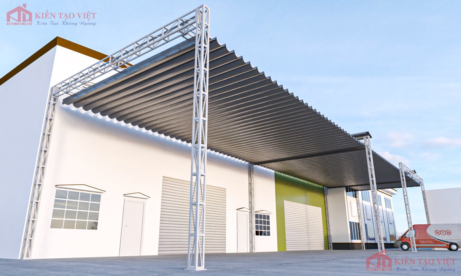
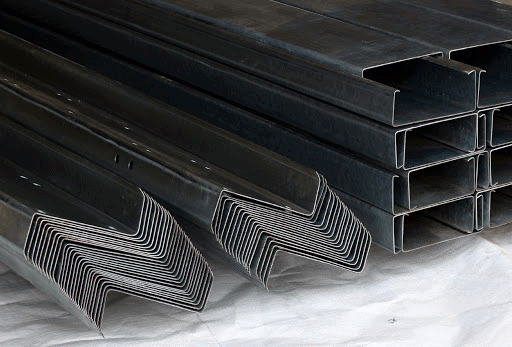
Purlins – The Load Distribution Members
Purlins are horizontal structural members that connect the arch frames and provide direct support for the PVC fabric or roofing panels installed above. They play a crucial role in distributing loads evenly across the structural frame.
Without a properly designed purlin system, the roof covering may sag, vibrate excessively, or lose structural stability, ultimately affecting the safety and durability of the entire canopy system.
Typical Technical Specifications
| Item | Specification |
|---|---|
| Material | Galvanized steel box sections |
| Common Sizes | 40 × 60 mm, 40 × 80 mm, 50 × 100 mm |
| Steel Thickness | 1.8-2.5 mm |
| Installation Spacing | 500-900 mm |
Functions
– Supports the roof covering material.
– Distributes loads evenly to the main structural frame.
– Increases the overall rigidity of the structure.
– Reduces roof deflection and sagging.
Bracing System – Enhancing Structural Stability
The bracing system connects the steel arch frames into a unified structural assembly, significantly improving overall stability and minimizing vibration or lateral movement under strong wind conditions.
The most commonly used bracing configurations include X-bracing, V-bracing, and K-bracing, each selected according to the structural span and design requirements.
Typical Technical Specifications
| Item | Specification |
|---|---|
| Material | Steel box sections or steel angle bars |
| Common Sizes | L40, L50, 40 × 40 mm, 50 × 50 mm |
| Bracing Types | X, V, K |
Functions
– Prevents frame twisting and distortion.
– Minimizes structural vibration.
– Improves wind resistance.
– Maintains the overall shape and stability of the canopy.
>>Learn more: Proper and Effective Roof Cleaning Guide
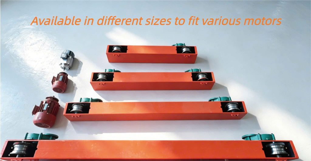
Wheel System – The Key Component for Smooth Movement
The wheel system is the critical mechanism that allows the entire motorized retractable dome canopy to move smoothly and accurately along the guide rails.
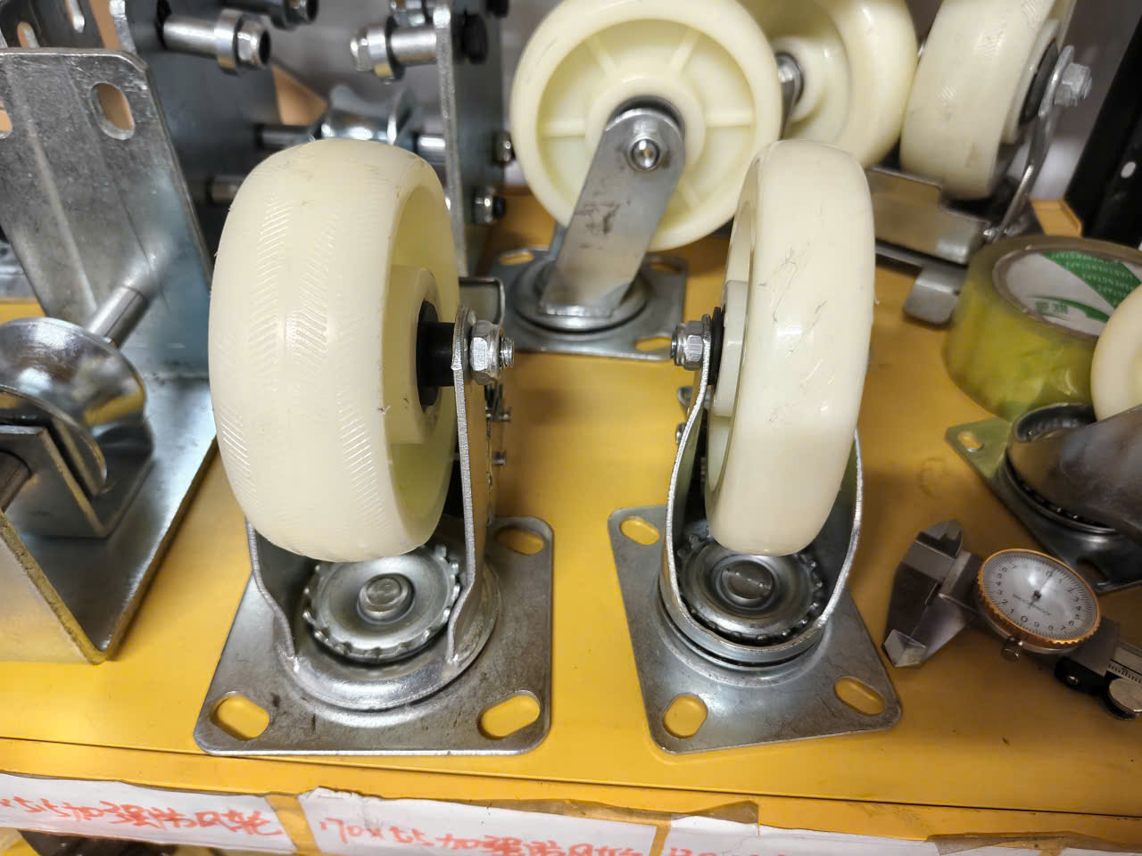
Depending on the structural design and load requirements, each roof module is typically equipped with 2 to 4 wheels, ensuring stable movement, even load distribution, and long-term operational reliability.
Typical Technical Specifications
| Item | Specification |
|---|---|
| Material | Ductile cast iron, C45 carbon steel, polyurethane (PU) |
| Wheel Diameter | 80–200 mm |
| Load Capacity | 200–1,500 kg per wheel |
| Bearing Service Life | 30,000–50,000 operating hours |
Functions
– Reduces friction during operation.
– Ensures smooth and stable roof movement.
– Supports the load of the entire structural frame.
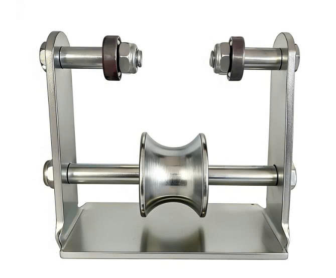
Guide Rail System – Ensuring Accurate Movement
The guide rail system provides the track on which the wheel assemblies travel, ensuring that each roof module moves smoothly and follows the correct path during opening and closing operations.
The two most common guide rail configurations are:
– Recessed guide rails (embedded in the ground)
– Surface-mounted guide rails
Typical Technical Specifications
| Item | Specification |
|---|---|
| Rail Profile | V-shaped, U-shaped, or I-beam rails |
| Rail Thickness | 6-12 mm |
| Rail Height | 50-120 mm |
| Load Capacity | 3-20 tons |
Functions
– Guides the movement of the roof modules.
– Minimizes vibration during operation.
– Supports and transfers loads from the wheel assemblies.
Drive System – Controlling the Opening and Closing Operation
Depending on the project scale and operational requirements, a motorized retractable dome canopy can be operated either manually or by an electric motor-driven system. While manual systems are suitable for smaller installations, electric drive systems are preferred for larger canopies due to their convenience, efficiency, and ease of operation.
Typical Technical Specifications
| Item | Specification |
|---|---|
| Motor Power | 0.37-2.2 kW |
| Operating Voltage | 220V or 380V |
| Opening/Closing Speed | 8-20 m/min |
| Control Options | Remote control, wall switch, or smartphone (depending on the system configuration) |
Functions
– Provides the driving force required to move the roof.
– Controls the opening and closing operation efficiently.
– Reduces manual labor and improves operational convenience.
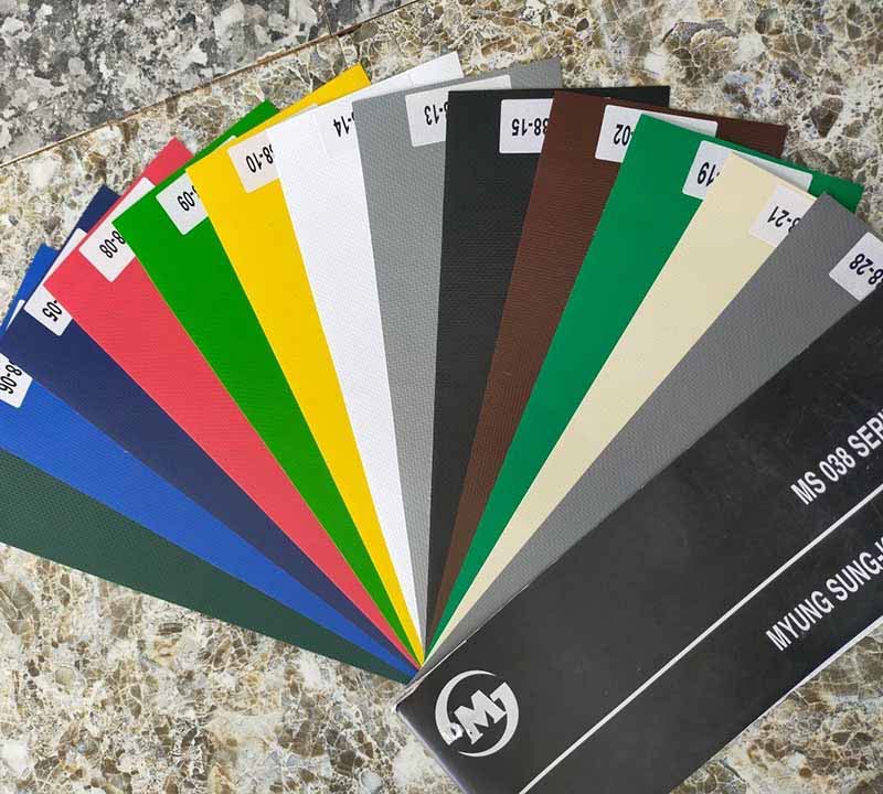
Roofing Materials
The roof covering material plays a crucial role in determining the canopy’s weather resistance, thermal performance, and overall service life. The two most commonly used roofing materials for a motorized retractable dome canopy are PVC-coated fabric and polycarbonate panels, each offering unique advantages depending on the application.
Typical Technical Specifications
| Item | PVC-Coated Fabric | Polycarbonate Panels |
|---|---|---|
| Thickness | 650-1,050 g/m² | 6-12 mm |
| Water Resistance | 100% waterproof | 100% waterproof |
| UV Protection | Blocks approximately 90–99% of UV rays | UV-resistant |
| Light Transmission | Opaque | 60-90% |
| Expected Service Life | 8-15 years | 10-20 years |
Functions
– Provides effective protection against rain.
– Reduces solar heat gain and improves thermal comfort.
– Protects against harmful ultraviolet (UV) radiation.
– Safeguards the space, equipment, and occupants beneath the canopy.
Drainage System
The drainage system is designed to channel rainwater along the curved surface of the roof into the gutter system, where it is then directed to downpipes for efficient water discharge. A well-designed drainage system helps prevent water accumulation, reduces structural loads, and extends the service life of the roofing material.
Typical Technical Specifications
| Item | Specification |
|---|---|
| Gutter Width | 150-300 mm |
| Gutter Slope | 0.5-1% |
Functions
– Collects rainwater efficiently.
– Prevents water ponding on the roof surface.
– Protects the roofing material and extends its service life.
Anchor Bolts and Concrete Foundation
The entire load of the motorized retractable dome canopy is transferred safely to the ground through the anchor bolt system and reinforced concrete foundation. These components are essential for ensuring the structural stability and long-term safety of the canopy, especially under heavy wind loads.
Typical Technical Specifications
| Item | Specification |
|---|---|
| Anchor Bolt Size | M16-M30 |
| Bolt Strength Grade | 8.8-12.9 |
| Anchor Embedment Depth | 250-600 mm |
| Concrete Strength | C25/30 or C30/37 |
Functions
– Secures the steel structure firmly to the foundation.
– Prevents overturning during strong wind conditions.
– Ensures long-term structural stability and safety.
Working Principle of a Motorized Retractable Dome Canopy
A motorized retractable dome canopy operates using a sliding modular system that travels along specially designed guide rails. Each roof section moves in a coordinated sequence, allowing the canopy to open and close smoothly while maintaining structural stability.
The operating process consists of the following steps:
Step 1: The user activates the system either manually or by using the electric motor control.
Step 2: The electric motor generates driving force and transmits it to the wheel assemblies through the drive mechanism.
Step 3: The wheels roll smoothly along the guide rails, moving each roof module in a controlled and synchronized manner.
Step 4: The arch frames, which are manufactured in progressively smaller sizes, telescope (nest) into one another. This telescopic design allows the canopy to retract compactly, reducing its occupied space to approximately 15-30% of its fully extended footprint.
Step 5: Once the canopy reaches the desired position, limit switches or mechanical locking devices secure the roof safely in place, preventing unintended movement during operation.
Thanks to this telescopic sliding mechanism, a motorized retractable dome canopy can be fully opened or closed within just a few minutes, maximizing usable space while allowing natural daylight and ventilation whenever required.
Key Advantages of a Motorized Retractable Dome Canopy
| Criteria | Specification |
|---|---|
| Flexible Opening and Closing | Operates according to user requirements |
| Installation Time | 3-15 days |
| Steel Frame Service Life | 20-30 years |
| PVC Fabric Service Life | 8-15 years |
| Water Resistance | 100% waterproof |
| Typical Wind Resistance | Designed to withstand Beaufort Scale 8-10 winds (depending on structural design) |
| Retracted Roof Size | Approximately 15-30% of the fully extended roof area |
These advantages make a motorized retractable dome canopy a cost-effective alternative to permanent roof structures. It offers greater flexibility in space utilization, reduces construction costs, and helps lower long-term operating and maintenance expenses for industrial, commercial, and recreational facilities.
>>Related Article: Essential Considerations Before Outdoor Canopy Construction and Canopy Installation
Conclusion
A motorized retractable dome canopy is an advanced roofing solution composed of several integrated structural components, including the steel arch frame, purlins, bracing system, guide rails, wheel assemblies, drive mechanism, roofing materials, and foundation system. Each component performs a specific function while working together to ensure the canopy operates safely, smoothly, and reliably over many years.
To maximize the service life and performance of the system, property owners should work with experienced designers, fabricators, and installation contractors. Proper engineering calculations including structural loads, roof span, wind loads, foundation conditions, and environmental factors are essential to achieving a safe and durable installation.